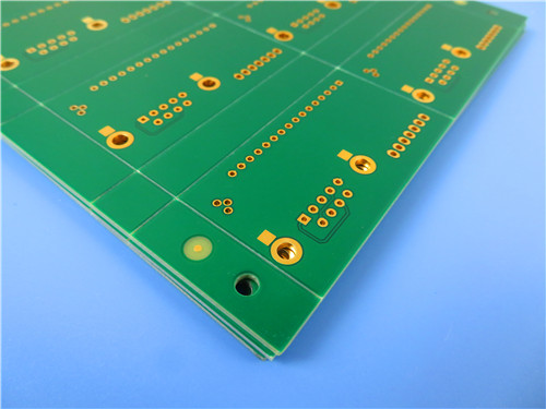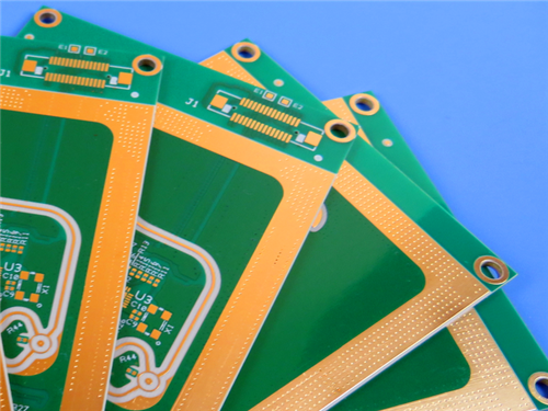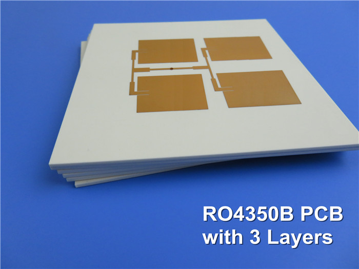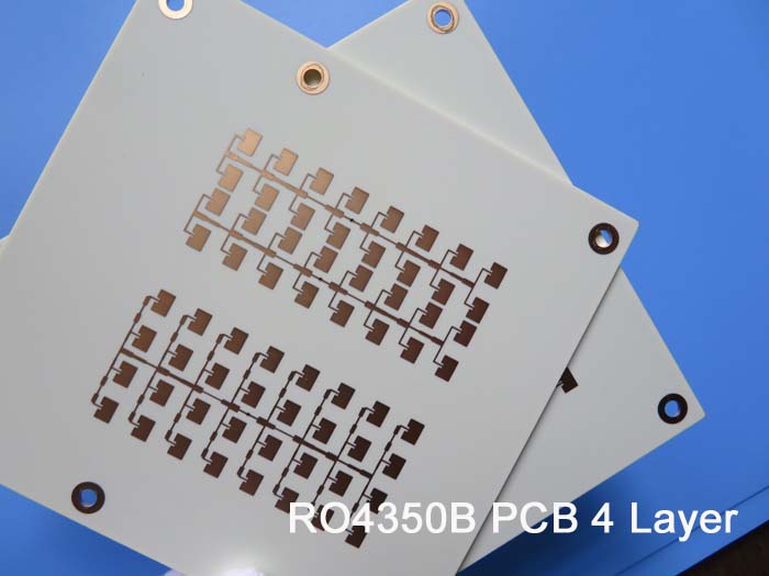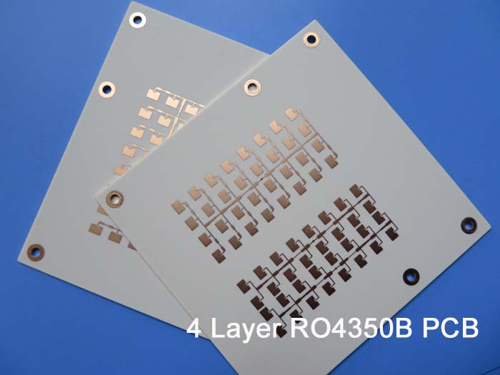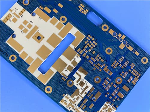
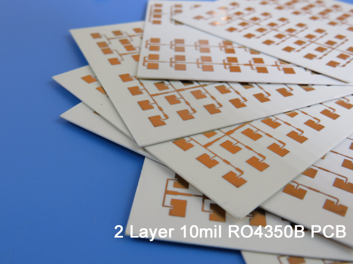
Rogers RO4350B LoPro 2-Layer 0.2mm Immersion Gold PCB – RF & High-Speed Digital Applications1. Introduction to Rogers RO4350B LoPro PCB RO4350B LoPro laminates use a proprietary Rogers technology that allows reverse treated foil to bond to standard RO4350B dielectric. This results in a laminate with low conductor loss for improved insertion loss and signal integrity while maintaining the other desirable attributes of the standard RO4350B laminate system. RO4350B hydrocarbon ceramic laminates are designed to offer superior high frequency performance and low cost circuit fabrication. The result is a low loss material which can be fabricated using standard epoxy/glass (FR-4) processes and does not require specialized via preparation such as sodium etch for lower manufacturing cost. The selection of laminates typically available to designers is significantly reduced once operational frequencies increase to 500 MHz and above. RO4000 material possesses the properties needed by designers of RF microwave circuits, matching networks, and controlled impedance transmission lines. Low dielectric loss allows RO4000 series material to be used in many applications where higher operating frequencies limit the use of conventional circuit board laminates. The temperature coefficient of dielectric constant is among the lowest of any circuit board material and the dielectric constant is stable over a broad frequency range, making it an ideal substrate for broadband applications. This 2-layer rigid PCB is constructed entirely with Rogers RO4350B LoPro as the core material, making it ideal for demanding RF, cellular base station, high-speed digital, and satellite communication applications.
2. Key Features of Rogers RO4350B LoPro PCB Dielectric constant of 3.48 ± 0.05 at 10 GHz/23°C Dissipation factor of 0.0037 at 10 GHz/23°C Td > 390°C, high Tg greater than 280°C (TMA) High thermal conductivity of 0.69 W/(m·K) Low Z-axis CTE of 32 ppm/°C Copper-matched CTE: X-axis 10 ppm/°C, Y-axis 12 ppm/°C (-55°C to 288°C) UL 94 V-0 flammability rating Lead-free process compatible CAF resistant 3. Benefits of Rogers RO4350B LoPro PCB Lower insertion loss allows for higher operating frequency designs (even greater than 40 GHz) Reduced passive inter-modulation (PIM) for base station antennas Improved thermal performance due to lower conductor loss Multilayer PCB capability Design flexibility High temperature processing Meets environmental concerns CAF resistant Can be fabricated using standard FR-4 processes without specialized via preparation Excellent dimensional stability with CTE similar to copper Reliable plated through-hole quality even in severe thermal shock applications 4. Rogers RO4350B LoPro PCB Construction Details
5. PCB Stackup (2-Layer Rigid Structure) Copper_layer_1 - 35 μm (1 oz) Rogers RO4350B LoPro Substrate - 4 mil (0.102 mm) Copper_layer_2 - 35 μm (1 oz) 6. PCB Statistics Components: 24 Total Pads: 49 Thru Hole Pads: 31 Top SMT Pads: 18 Bottom SMT Pads: 0 Vias: 26 Nets: 2 7. Primary Application Areas Digital applications such as servers, routers, and high speed back planes Cellular base station antennas and power amplifiers LNBs for direct broadcast satellites RF identification tags RF microwave circuits and matching networks Controlled impedance transmission lines Broadband applications 8.Quality Assurance Type of artwork supplied: Gerber RS-274-X Accepted standard: IPC-Class-3 Availability: Worldwide 9. Rogers RO4350B LoPro Hydrocarbon Ceramic Laminate – Product Introduction RO4350B LoPro laminates use a proprietary Rogers technology that allows reverse treated foil to bond to standard RO4350B dielectric. This results in a laminate with low conductor loss for improved insertion loss and signal integrity while maintaining all other desirable attributes of the standard RO4000 laminate system. RO4000 hydrocarbon ceramic laminates are designed to offer superior high frequency performance and low cost circuit fabrication. The result is a low loss material which can be fabricated using standard epoxy/glass (FR-4) processes offered at competitive prices. The selection of laminates typically available to designers is significantly reduced once operational frequencies increase to 500 MHz and above. RO4000 material possesses the properties needed by designers of RF microwave circuits and matching networks and controlled impedance transmission lines. Low dielectric loss allows RO4000 series material to be used in many applications where higher operating frequencies limit the use of conventional circuit board laminates. The temperature coefficient of dielectric constant is among the lowest of any circuit board material and the dielectric constant is stable over a broad frequency range. This makes it an ideal substrate for broadband applications. RO4000 material's thermal coefficient of expansion (CTE) provides several key benefits to the circuit designer. The expansion coefficient of RO4000 material is similar to that of copper which allows the material to exhibit excellent dimensional stability, a property needed for mixed dielectric multilayer boards constructions. The low Z-axis CTE of RO4000 laminates provides reliable plated through-hole quality, even in severe thermal shock applications. RO4000 series material has a Tg of >280°C (536°F) so its expansion characteristics remain stable over the entire range of circuit processing temperatures. RO4000 series laminates can easily be fabricated into printed circuit boards using standard FR-4 circuit board processing techniques. Unlike PTFE based high performance materials, RO4000 series laminates do not require specialized via preparation processes such as sodium etch. This material is a rigid, thermoset laminate that is capable of being processed by automated handling systems and scrubbing equipment used for copper surface preparation.
10. Features and Benefits Summary
11. Rogers RO4350B LoPro Data Sheet
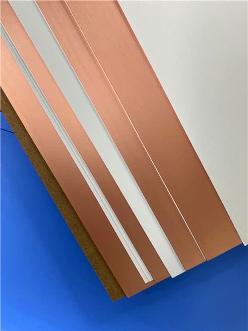
12. Some Typical Applications Digital applications such as servers, routers, and high speed back planes Cellular base station antennas and power amplifiers LNBs for direct broadcast satellites RF identification tags RF microwave circuits and matching networks Controlled impedance transmission lines Broadband applications 13. Standard Thicknesses, Panel Sizes & Claddings Standard Thicknesses (RO4350B LoPro)
Standard Panel Sizes 12" x 18" (305 x 457 mm) 24" x 18" (610 x 457 mm) 24" x 36" (610 x 915 mm) 48" x 36" (1219 x 915 mm) Note: Additional panel sizes available. Standard Claddings LoPro Reverse Treated Electrodeposited Copper Foil: ½ oz (18 μm), 1 oz (35 μm) Additional Notes Bow and Twist: Outgoing inspection criteria for flatness is <6% Bow and <6% Twist Electrical Strength: 4 mil dielectric thickness can withstand 1,500 volts without dielectric breakdown Dimensional Stability: Negative nominal value of approximately -0.5 mm/m in both MD and CMD directions Dielectric Constant: LoPro resin layer is a significant volumetric portion of the overall dielectric, design Dk will be different than thicker constructions |
Get a Quick Quote
Fill in the form below and our engineers will reply within 24 hours with technical specifications and pricing for Rogers RO4350B LoPro 2-Layer 0.2mm Immersion Gold PCB.
.jpg)